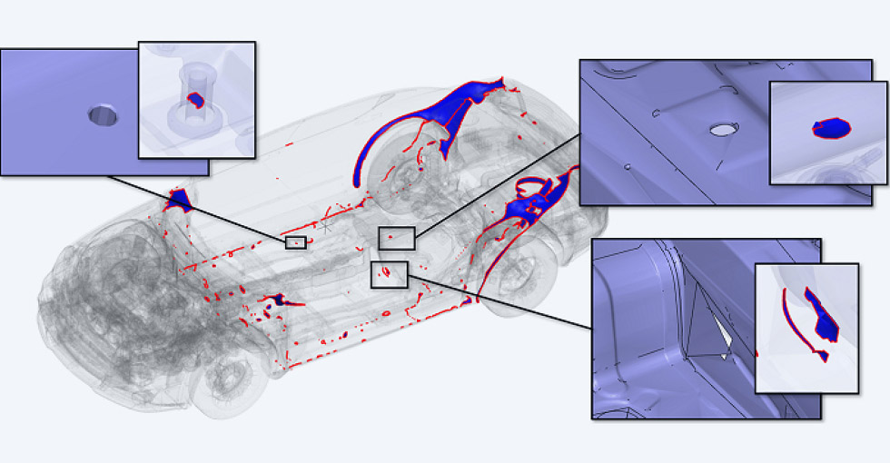
SEALS, which is an acronym for Super-Efficient Automatic Leakage Stopper, finds and closes mesh leakage paths between internal and external volumes. The basic process is to use the exterior meshing capability of the General Mesher to initially create a mesh that includes both the internal and external volumes. SEALS is then used to detect any leaks, where the fluid mesh enters unintended regions and then close these gaps.
In some cases, detecting leaks can be challenging using standard CAD based capabilities. In such instances, this feature proves highly effective by automating the detection process, thereby reducing manual effort, significantly saving time, and simplifying the CAD cleanup. It identifies and seals all the gaps with a single click, enabling the extraction of the fluid domain and the separation of internal and external volumes as per user requirements. Once the leaks are closed, the same mesh can be used for the simulation, eliminating the need for remeshing.
Leak Closure (SEALS) Features
This section explains the various options available in the Leak Closure (SEALS) to find and close the unwanted gaps inside the geometry:
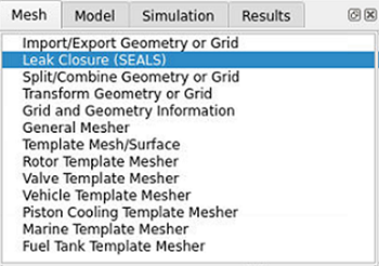
You can access this feature from the Mesh panel as shown here.
Inside Definition
The first step is to define where the interior volumes are in the model using either:
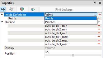
Points: Uses a predefined monitor point that needs to be placed at a co-ordinate location that is known to be within the interior fluid region. The position and number of points should be adjusted to effectively capture the leak path. Multiple points can be used for bigger and complex geometry:
Note: It can help to define the Points near likely gap locations, where the probability of leakage is higher.
Patches: Is used to select a surface patch that is within the interior fluid region. This surface needs to be defined before the geometry is meshed. The position and number of patches should be adjusted to effectively capture the leak path. It is beneficial for large models with known gaps, as it simplifies the process compared to creating individual point sources.
Note: It helps to define the Patches near likely gap locations, where the probability of leakage is higher.
Find Leakage
Clicking this action button identifies all the leakage paths by creating an iso-surface of the fluid within the volume.
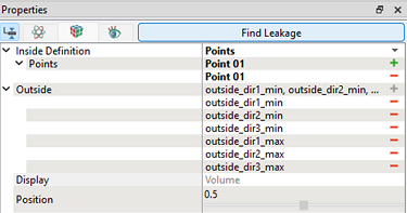
Display
- Volume: Provides a preview of the internal volume after sealing the leakage, showing the retained fluid domain. This allows the user to verify the fluid volume before proceeding.
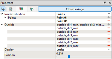
- Leaks: Provides the cross-sectional view of the leakage path, indicating the region from which the fluid is escaping.
Position
It is used to separate the desired fluid volume either by defining the quantity or by adjusting the slider. It is a scalar quantity which can be varied between 0 to 1. A lower value allows the fluid volume to spread further from the specified interior point or patch.
Close Leakage
Once the Find Leakage step is completed the action button at the top of the panel changes to Close Leakage. Once the user has selected a relevant position click on this and the mesh volume will be split in two based on the surface shown. Once this seperation is complete additional volume entities will appear in the Geometric Entities panel. From here the user can decide whether to delete the interior or exterior volume or retain both depending on the purpose of the simulation.